Beginner sequence · Step 2 of 3
Start here
Readiness check: Students can identify the power source, input or switch, and output in a picture. Before class, rehearse the exact safe build with the listed components.
Exact starter recipe
POWER OFF. Arrange and label the parts first.
Teacher-approved power (+) → input or switch → output with its required resistor/module → power (−).
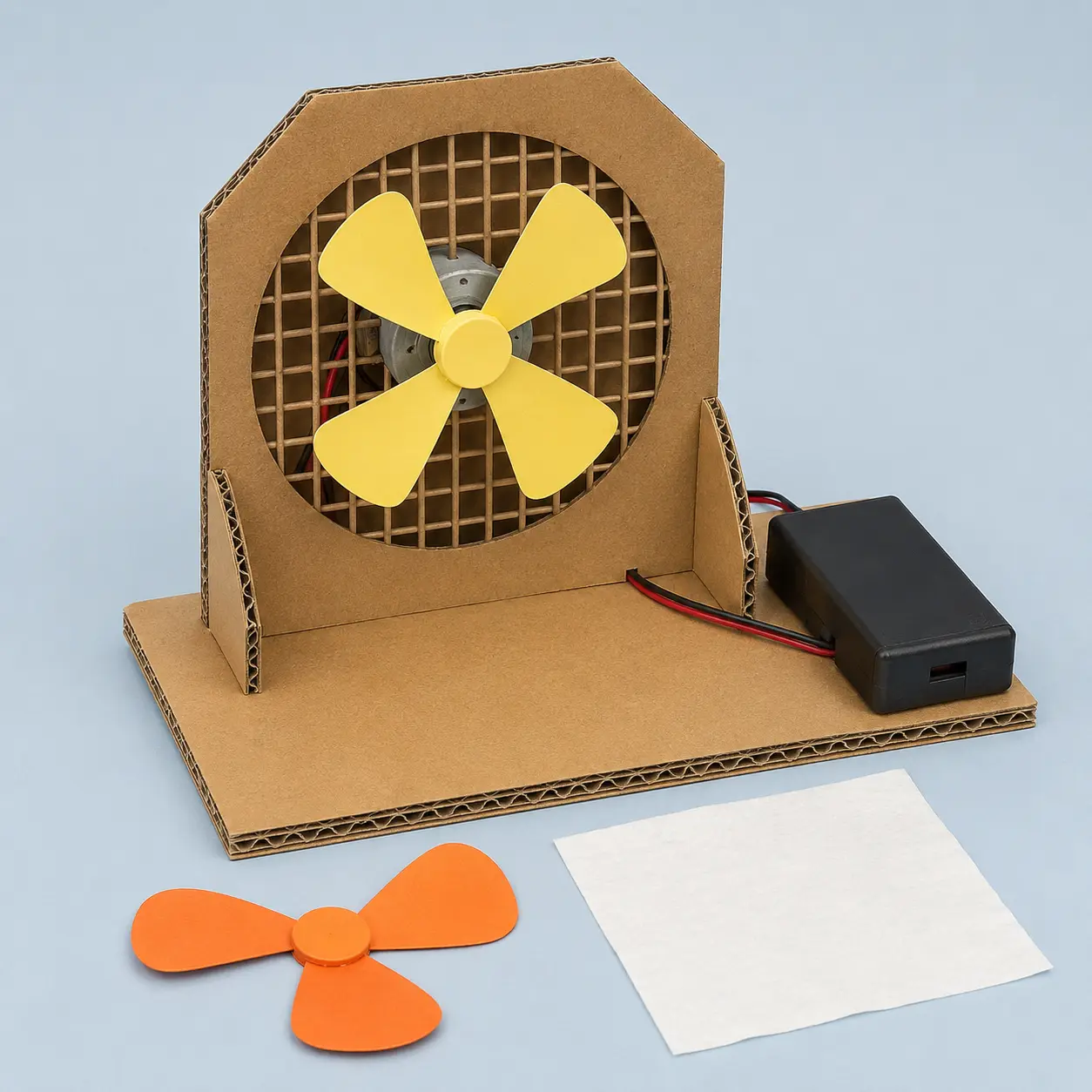
For this project: Create two equal-mass blade sets. An adult fits each set to the hub; students secure the motor and full guard before any powered test.
Teacher checks the complete path before power-on. Disconnect power before every change.
Make the simplest version work first. Then use the test and extension in this lesson.
Teacher learning resources
Preview external resources before class. The circuit reference explains the science; use this page’s specified AA kit and connection list for the build.
For teachers
Engineering standards
This shows how the lesson connects to the national NGSS engineering standards and what student work you can collect.
3-5-ETS1-1
Define the job of the mini fan blade test, its two success checks and the low-voltage safety limits.
What students show: Labeled input–output plan with criteria and constraints.3-5-ETS1-2
Compare two layouts or control ideas before choosing the easiest safe version to build and test.
What students show: Two small sketches and one criteria-based choice.3-5-ETS1-3
Use the same procedure for repeated trials: Run each blade set for five seconds from the same distance in three trials and measure tissue movement. Change one feature and repeat.
What students show: Before-and-after test record and evidence-based explanation.Materials
- two-AA covered battery holder
- 1.5–3 V hobby motor
- teacher-fitted hub
- paper blades
- cardboard guard
- tissue target
- Planning pencil, circuit map, data table and printable student brief
- Color-coded component labels and teacher-prepared insulated leads
Teacher preparation
- Gather and verify these exact parts: two-AA covered battery holder; 1.5–3 V hobby motor; teacher-fitted hub; paper blades; cardboard guard; tissue target.
- Build and test one reference circuit using the manufacturer ratings; prepare a large color-coded connection diagram.
- Prepare the project structure and difficult cuts, stripped leads, motor hubs or sensor modules before students arrive.
- Set up a clearly marked POWER OFF build area, adult-check point and short powered-test area.
- Print the student brief and make a troubleshooting card: battery orientation → secure clips → resistor/module → LED polarity → switch gap.
Step by step
How to teach it
Name the job
- Compare two lightweight paper fan-blade designs on the same guarded low-voltage motor.
- Point out the input or switch and output. Read the two success checks and safety limits.
Model the circuit
- Teach motor outputs and fair testing with a large diagram.
- Trace one complete path from positive to negative. Model power off before touching any connection.
Build with power off
- Create two equal-mass blade sets. An adult fits each set to the hub; students secure the motor and full guard before any powered test.
- Partners compare the real build with the diagram. No pair powers on before the adult check.
First safe trial
- Teacher checks voltage, resistor/module, polarity, secure parts and shorts.
- Run one brief trial, disconnect power and circle the first problem to fix.
Predict and reconnect
- Review the diagram and safety stop signs. Predict the test result.
- Reconnect only after the pair can explain the intended path.
Test and record
- Run each blade set for five seconds from the same distance in three trials and measure tissue movement.
- One partner operates while the other records; swap roles and keep conditions the same.
Troubleshoot one thing
- Disconnect power. Check one point at a time: source, connection, component direction, control, output.
- Change one feature, receive another adult check and repeat the test.
Explain and pack safely
- Demonstrate the working input-to-output action and use one recorded result in the explanation.
- Disconnect power. Adult collects batteries and modules; students return remaining parts.
Assessment
- Motor stays secured behind the guard
- Comparison changes blade shape while holding test conditions steady
- Student points to and names the power source, input/control and output.
- Build follows the teacher diagram and power-off safety routine.
- Student records repeated results and explains one revision.
Supports & extensions
- Provide a full-size color-coded diagram and place matching colored labels beside the real terminals.
- Offer preconnected resistor–LED modules, larger switches or prepared structures while preserving the input–output reasoning.
- Let students direct a partner, point to a diagram or dictate test evidence.
- Test the smallest working circuit before attaching it to the creative project.
- Extension after success: add one clearly labeled control or compare a second setting without changing the safe power source.
Safety & responsible use
- Use only the exact teacher-approved covered battery pack or classroom module listed; never use wall power, lithium cells, coin/button cells, or unknown power supplies.
- Power must be OFF before building or changing any connection. The teacher checks voltage, resistor values, polarity and possible shorts before power-on.
- Never connect battery terminals directly. Stop immediately and disconnect power if a component becomes warm, leaks, smells unusual or behaves unpredictably.
- Adults prepare wire ends, motor hubs and difficult holes. Cover sharp leads, secure moving parts, wear eye protection for guarded motor tests and keep liquids in a separate tray.
No-machine alternative
Test the same paper blades on a hand-spun blunt axle and measure tissue movement.
Printable student design brief
The challenge
Compare two lightweight paper fan-blade designs on the same guarded low-voltage motor.
Success criteria
- Motor stays secured behind the guard
- Comparison changes blade shape while holding test conditions steady
- Explain the power source → input/control → output path
Constraints
- Use only the listed teacher-approved low-voltage parts
- Power off before every connection change; adult approval before power-on
- No soldering, wall power, lithium cells or coin/button batteries
- Complete the working system and test record before decoration
Engineer’s notes
Printable beginner test record
Predict. Try. Improve.
Name ____________________ Partner ____________________
Our success rule: __________________________________________________
| Trial | Input / action | Expected result | First result | Result after one change |
|---|---|---|---|---|
| 1 | ||||
| 2 | ||||
| 3 | ||||
| 4 | ||||
| 5 | ||||
| 6 | ||||
| 7 | ||||
| 8 | ||||
| 9 | ||||
| 10 |
Use three rows for the introductory tests or all ten for switch reliability. Write the held, released, or other-key state for each sensing test.
One thing we changed: ______________________________________________
Things we kept the same: ____________________________________________
Our evidence shows: _________________________________________________